Call Point for Fire Alarm/Manual Alarm Button
2.Working current:
1)Standby current:≤0.5mA
2)Alarm current:≤2.3mA
3. Output capacity: rated DC30V / 100mA passive output contact signal, contact resistance ≤ 100mΩ
4. Start part type: reusable type
5. Start mode: manually press the chip
6. Reset mode: reset with a dedicated key. After the product alarm, open the alarm button key cover (Figure 1) insert the special key to the right twist 90 degrees, the product can be reset.
7.Indication status: Indication status:
1)fire lights, red, normal patrol when the periodic flashing, after the alarm is always on, the lights off when the failure or irregular flash
2) phone lights, red, about 6s flash once
8.Type: connected with the controller with nonpolarity two bus types, with a fire alarm system with nonpolarity two bus connections
9.Encoding: Electronic code,encoding range(1~242)
10. Operating environment: indoor,Temperature-10ºC~50ºC ,Relative humidity≤95%RH,No condensation
11. Shell material and Color:ABS,red
12.Protection class:IP43
13. Weight: about 95g (with base)
14. Dimensions: 90mm×90mm×33mm
15. Mounting hole distance:60mm
16.Executive standard:GB 19880-2005,GB 16806-2006
2. Using hardware and software filtering to improve the anti-interference ability of the manual call point
3.Use dedicated keys to reset after the chip is pushing down
4. The alarm button provides independent output contacts for direct controlling of other external devices
5. The address code is electronic code, which can be rewritten on site
Figure 1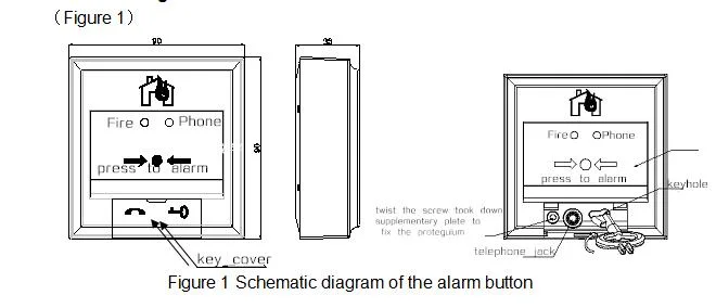
Schematic diagram of the alarm button
Alarm button installation (Figure 2)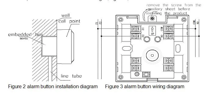
2.Wiring:
Insert a special key, you can open alarm base and the cover. Wiring as shown in Figure 3, load the manual call point to the base after wiring. Twist the screw took down from supplementary plate to fix the cover to the base, and pay attention to the installation direction, and the installation orientation logo(Figure 3)
Figure 2 alarm button installation diagram
A. Specifications
1.Working voltage: addressable 15-28V Impulse voltage2.Working current:
1)Standby current:≤0.5mA
2)Alarm current:≤2.3mA
3. Output capacity: rated DC30V / 100mA passive output contact signal, contact resistance ≤ 100mΩ
4. Start part type: reusable type
5. Start mode: manually press the chip
6. Reset mode: reset with a dedicated key. After the product alarm, open the alarm button key cover (Figure 1) insert the special key to the right twist 90 degrees, the product can be reset.
7.Indication status: Indication status:
1)fire lights, red, normal patrol when the periodic flashing, after the alarm is always on, the lights off when the failure or irregular flash
2) phone lights, red, about 6s flash once
8.Type: connected with the controller with nonpolarity two bus types, with a fire alarm system with nonpolarity two bus connections
9.Encoding: Electronic code,encoding range(1~242)
10. Operating environment: indoor,Temperature-10ºC~50ºC ,Relative humidity≤95%RH,No condensation
11. Shell material and Color:ABS,red
12.Protection class:IP43
13. Weight: about 95g (with base)
14. Dimensions: 90mm×90mm×33mm
15. Mounting hole distance:60mm
16.Executive standard:GB 19880-2005,GB 16806-2006
B. Features
1.Built-in product ID code2. Using hardware and software filtering to improve the anti-interference ability of the manual call point
3.Use dedicated keys to reset after the chip is pushing down
4. The alarm button provides independent output contacts for direct controlling of other external devices
5. The address code is electronic code, which can be rewritten on site
C. Outline diagram
(Figure 1)Figure 1
Schematic diagram of the alarm button
D. Installation
1.Installation method:Alarm button installation (Figure 2)
2.Wiring:
Insert a special key, you can open alarm base and the cover. Wiring as shown in Figure 3, load the manual call point to the base after wiring. Twist the screw took down from supplementary plate to fix the cover to the base, and pay attention to the installation direction, and the installation orientation logo(Figure 3)
Figure 2 alarm button installation diagram